Over-Extrusion: Signs Causes & Calibration Fix Guide
The most likely cause of over-extrusion is an incorrect extruder steps-per-millimeter (e-steps) calibration, not a slicer flow rate problem. When your printer pushes more filament than the firmware expects, every print suffers—walls bulge, dimensions grow, and top surfaces turn rough and ridged. The fix starts with measuring what your extruder actually pushes versus what it thinks it pushes, then adjusting the e-steps value stored in firmware. Below, we walk through the signs that confirm over-extrusion, the calibration steps that correct it, and the mechanical failures that slicer tweaks alone cannot solve.
What Over-Extrusion Looks Like on a Finished Print
Over-extrusion leaves a consistent fingerprint across multiple print features. Recognizing these signs early prevents wasted filament and hours of chasing the wrong setting.
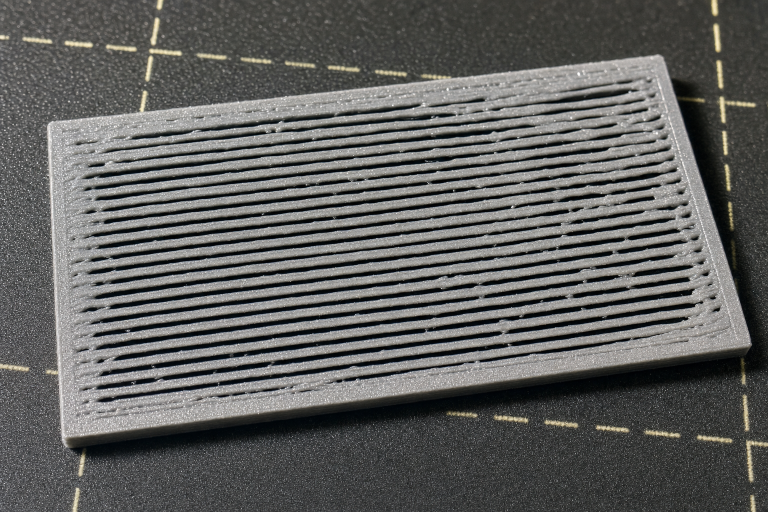
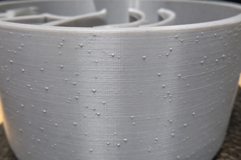
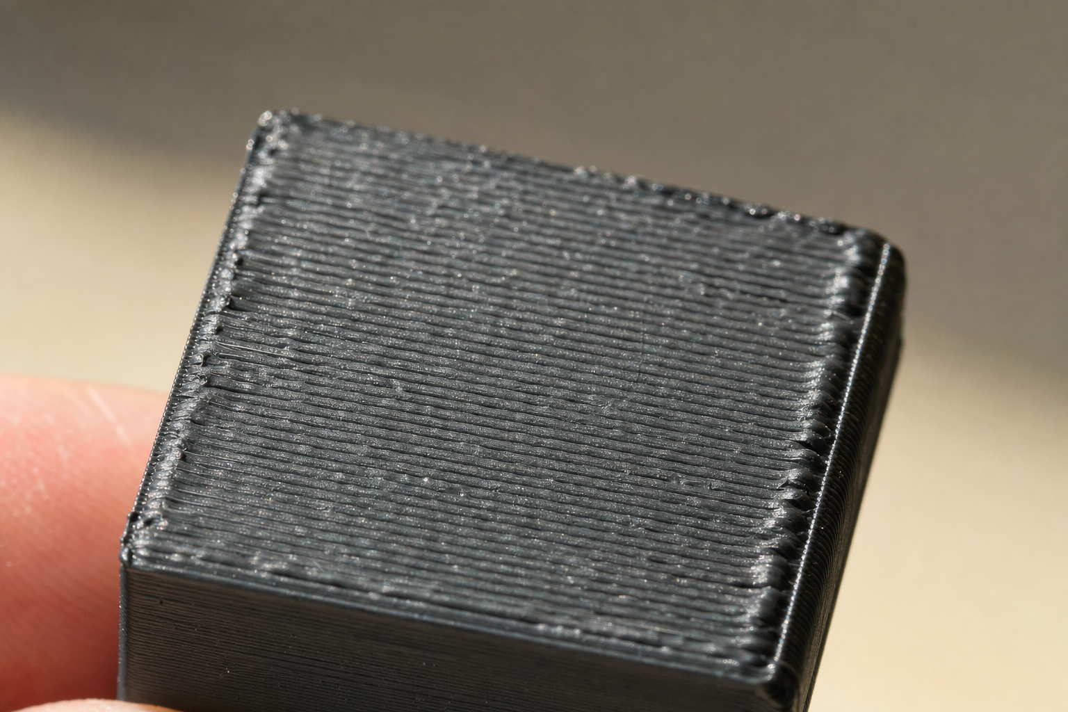
Top and bottom solid layers develop raised ridges, nozzle drag marks, or a rippled texture. The excess plastic has nowhere to escape, so the nozzle plows through previously laid lines and leaves visible scarring. On a flat top surface, you will see parallel grooves where the nozzle tip dragged through still-soft material.
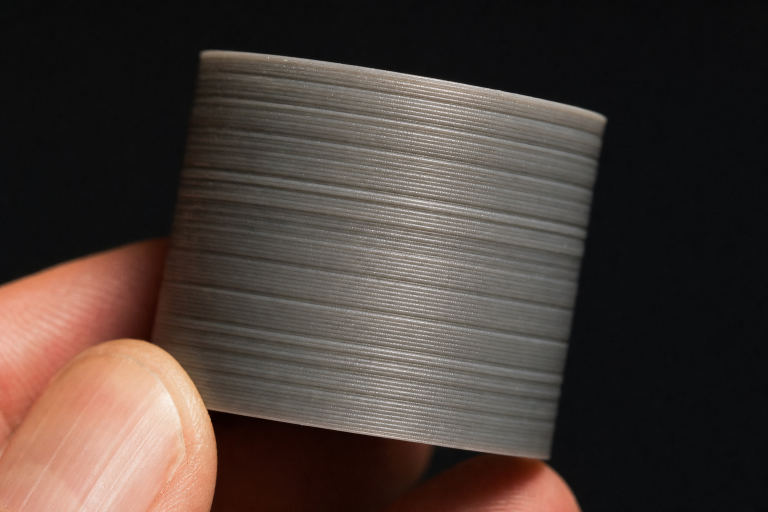
Vertical walls measure thicker than the slicer intended. A single-perimeter calibration cube printed at a 0.4mm line width might measure 0.48mm or more. This dimensional inaccuracy compounds on multi-part assemblies where fit tolerances are tight—a print-in-place mechanism that should move freely will seize.
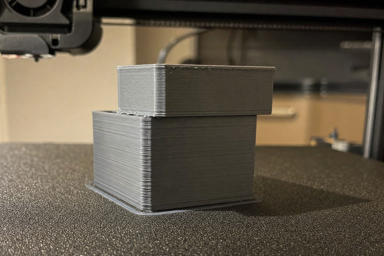
Corners and edges bulge outward. The nozzle deposits extra material at direction changes, creating a pillowed or rounded-over look on what should be a sharp corner. This is distinct from ringing artifacts—bulging from over-extrusion appears as a consistent swelling rather than a repeating wave pattern.
Small features and text fill in or lose definition. Embossed lettering on the side of a print becomes unreadable because the extra plastic bridges the gaps between characters. Holes print undersized, and press-fit tolerances disappear. A 3mm hole might print at 2.7mm, making bolt clearances fail.
Layer seams appear as raised blobs or zits rather than a subtle vertical line. While some seam visibility is normal, over-extrusion amplifies the seam into a pronounced ridge that runs the full height of the part. The blobs will be consistent in size and spacing, not random.
A quick differential test: if you see these symptoms across multiple filament types and brands, the problem is likely in the extruder calibration or mechanical system, not a single wet spool or bad temperature setting.
The One Failure Mode Most Owners Miss
Before you change any slicer setting, check for filament diameter inconsistency paired with an uncalibrated flow assumption.
Many slicer profiles default to 1.75mm filament diameter. Real filament varies—a spool labeled 1.75mm might measure 1.72mm or 1.78mm across its length. If your filament averages 1.78mm and your slicer assumes 1.75mm, the extruder pushes roughly 3.5% more volume than intended on every move. That alone produces the ridged top layers and bulging corners described above.
The early detection method is simple: take ten measurements along a two-meter section of filament with calipers, average them, and enter that value in your slicer’s filament diameter field. Do not rely on the spool label. A 0.03mm deviation sounds small, but the cross-sectional area difference scales with the square of the radius—small diameter errors produce outsized extrusion errors.
If your measured average falls outside 1.73–1.77mm, the filament itself is a contributor to over-extrusion before any printer setting is wrong. At that point, you have a choice: enter the true average into your slicer and proceed with calibration, or set that spool aside for non-critical prints where dimensional accuracy does not matter. If the diameter varies by more than 0.05mm across your ten measurements, the spool has poor manufacturing tolerance and will cause inconsistent extrusion even with correct calibration.
Quickest Checks Before Changing Any Setting
Run these three checks in order. Each takes under five minutes and rules out the most common non-calibration causes.
1. Nozzle Size Verification
Confirm the physical nozzle matches the slicer setting. A 0.4mm nozzle installed with a slicer profile set to 0.4mm is correct. If someone swapped to a 0.6mm nozzle and the profile stayed at 0.4mm, the printer over-extrudes dramatically because the slicer calculates volumes for a smaller orifice. Check the marking on the nozzle body—most have the diameter engraved on one flat of the hex. If the marking is worn off, measure with a pin gauge set or compare against a known new nozzle.
2. Filament Diameter Measurement
As described above, take ten measurements with calipers across several meters of filament. Enter the average into your slicer’s material settings. This is not a one-time step—repeat it when switching spools, especially across brands. A spool of budget PLA can differ from a premium PETG by 0.05mm or more.
3. Extruder Tension Check
Too much idler tension on a direct-drive or Bowden extruder deforms the filament and increases the effective drive radius. The extruder gear bites deeper, pushes more filament per rotation, and mimics an e-steps error. Back off the tension screw until the extruder grips reliably without leaving deep tooth marks. A light, even pattern on the filament surface is normal; gouges that reduce the filament diameter are not. If you see filament shavings collecting around the extruder gear, tension is too high.
If all three checks pass and over-extrusion persists, move to e-steps calibration.
E-Steps Calibration: The Core Fix
E-steps define how many motor steps correspond to 1mm of filament movement. A printer with e-steps set too high over-extrudes on every print, regardless of slicer flow rate adjustments.
Materials Needed
- Digital calipers with 0.01mm resolution
- Permanent marker or tape
- Terminal access (OctoPrint, Pronterface, or your printer’s LCD interface)
- The ability to save values to firmware (M500 command support or manual firmware recompilation)
Calibration Procedure
1. Heat the hotend to your normal printing temperature for the filament loaded. The extruder must push against realistic backpressure; cold calibration produces an artificially low e-steps value because there is no nozzle resistance.
2. Mark the filament 120mm above a fixed reference point—the extruder body entry or the top of a runout sensor housing. Use calipers to measure exactly 120mm and make a second mark at 20mm. You now have a 100mm test segment between your marks.
3. Extrude 100mm by sending `G1 E100 F100` through the terminal. The slow feed rate (F100, or 1.67mm/s) avoids skipped steps during measurement. Watch the filament move and listen for any clicking or skipping from the extruder motor.
4. Measure the remaining distance from the reference point to your 120mm mark. If 20mm remains, your extruder is calibrated. If 15mm remains, the printer extruded 105mm instead of 100mm—over-extrusion confirmed. If 28mm remains, it extruded only 92mm, indicating under-extrusion.
5. Calculate the new e-steps value:
- Read current e-steps with `M503` (look for the M92 line, e.g., `M92 X80 Y80 Z400 E93.0`)
- New e-steps = (Current e-steps × 100) ÷ Actual extruded length
- Example: (93 × 100) ÷ 105 = 88.6
6. Set and save the new value:
- `M92 E88.6`
- `M500` (saves to EEPROM on most firmware)
7. Repeat the measurement to confirm. A second pass should leave exactly 20mm remaining. A ±0.5mm tolerance is acceptable.
Verifying the Fix Worked
After saving the new e-steps value, print a simple 20mm calibration cube with single perimeter walls, zero infill, and zero top layers. Measure the wall thickness at the midpoint of each of the four sides with calipers and average the results. If your slicer is set to a 0.4mm extrusion width, the measured average should fall between 0.38mm and 0.42mm. A result within this range confirms the e-steps correction solved the over-extrusion. If walls still measure above 0.44mm, move to flow rate tuning below.
When E-Steps Calibration Is Not Enough
If your e-steps calibrate correctly but prints still show over-extrusion, the problem has moved downstream. The extruder is pushing the right amount of filament, but something else is forcing excess material out of the nozzle. That shifts the investigation to flow rate and mechanical issues.
Flow Rate Tuning: Fine Control After E-Steps
Flow rate (also called extrusion multiplier) is a per-filament slicer adjustment. It compensates for material-specific behavior—some PLAs expand more than others when melted, and flexible filaments often require different multipliers than rigid ones.
Calibration Method Using a Hollow Cube
Print a single-perimeter, zero-infill, zero-top-layer cube (20mm × 20mm × 20mm). Measure the wall thickness at the midpoint of each side with calipers. Average the four measurements.
If your slicer is set to a 0.4mm extrusion width and your measured average is 0.44mm, the flow rate is too high. The adjustment formula:
New flow rate = (Expected width ÷ Measured width) × Current flow rate
Example: (0.40 ÷ 0.44) × 100% = 90.9%
Apply this multiplier in your slicer’s material settings for that specific filament. Do not adjust the global flow rate on the printer LCD unless you are running a quick test—per-filament slicer settings are the correct long-term location.
Flow Rate Ranges by Material Type
| Material | Typical Flow Rate Range | Notes |
|---|---|---|
| PLA | 90–100% | Most PLAs print well at 95–98% after e-steps calibration |
| PETG | 92–98% | Slightly lower than PLA; over-extrusion causes heavy stringing |
| ABS | 95–100% | Density varies by brand; calibrate per spool |
| TPU (flexible) | 100–110% | Flexible filaments often need a slight increase, not decrease |
| Nylon | 95–100% | Dry filament is critical; wet nylon foams and mimics over-extrusion |
Flow rate below 90% usually indicates an unresolved e-steps error or a partial nozzle clog that was masked by previous over-extrusion settings. If your calculated flow rate falls below 90%, stop and re-check e-steps calibration and nozzle condition before proceeding.
Temperature as an Over-Extrusion Amplifier
Printing too hot does not directly cause over-extrusion, but it amplifies the visible symptoms. Excessively fluid filament oozes during travel moves, flows wider when deposited, and creates the same bulging corners and scarred top layers as a true e-steps error.
Diagnosing Temperature Contribution
Print a temperature tower that changes nozzle temperature every 5–10mm of Z-height. A model that steps from 220°C down to 190°C (for PLA) reveals the temperature band where over-extrusion symptoms disappear.
If the tower looks over-extruded at 215°C but clean at 200°C, your e-steps and flow rate may be correct, but your normal printing temperature is too high for that specific filament. Drop the temperature 10–15°C and re-evaluate.
Material-Specific Temperature Ceilings
- PLA: Over-extrusion symptoms often appear above 210–215°C on standard formulations. Silk and matte PLAs may need different ceilings.
- PETG: Stringing and bulging increase sharply above 245–250°C. Most PETG prints cleanly at 230–240°C.
- ABS: Over-extrusion signs above 255–260°C, though enclosure temperature also affects behavior.
- TPU: Temperature sensitivity varies widely by shore hardness; calibrate per brand.
A temperature tower costs 30 minutes and 5 grams of filament. It answers the temperature question definitively and prevents days of chasing phantom calibration errors.
Mechanical Causes That Mimic Over-Extrusion
Some failures produce over-extrusion symptoms but cannot be fixed with e-steps, flow rate, or temperature adjustments. These require mechanical intervention.
Partial Nozzle Clog with Pressure Buildup
A partial clog restricts flow, so the extruder builds pressure behind the obstruction. When pressure finally releases, it pushes excess material in bursts, creating alternating under-extruded and over-extruded sections. The telltale sign: inconsistent extrusion that changes within a single print layer. A cold pull (atomic pull) clears the obstruction. Heat the nozzle to printing temperature, insert cleaning filament or nylon, let it cool to 90°C for PLA or 140°C for PETG, then pull firmly. If cold pulls fail repeatedly or the pulled filament shows no debris, replace the nozzle.
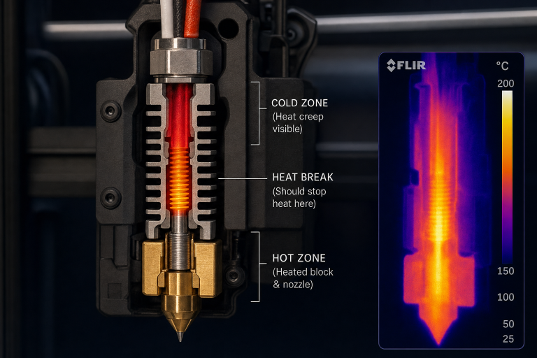
Heat Creep
When heat travels up the hotend heat break, filament softens too early and expands in the cold zone. The extruder motor works harder to push the swollen filament, and when it finally moves, the excess softened material exits the nozzle as a blob. Heat creep symptoms worsen over the first 20–30 minutes of a print. Check that the hotend cooling fan runs at full speed from the moment the hotend reaches 50°C and that the heatsink fins are clean. A failing hotend fan that spins slowly or intermittently is the most common root cause.
Worn Extruder Gear
Brass extruder drive gears wear over time, especially with abrasive filaments (glow-in-the-dark, carbon-fiber-filled). A worn gear develops a groove that changes the effective drive diameter, making e-steps calibration inconsistent. If your e-steps value drifts week to week or you see brass-colored dust around the extruder, replace the drive gear. Hardened steel gears last longer with abrasive materials.
Z-Axis Binding
If the Z-axis does not move the commanded layer height, each layer gets squished into the previous one, forcing material outward and mimicking over-extrusion on vertical walls. The diagnostic sign: over-extrusion symptoms that worsen near the bottom of the print and improve higher up, or a pattern that repeats with the Z leadscrew pitch. Check leadscrew coupler tightness, brass nut wear, and gantry alignment. Manually rotate the leadscrew by hand with the steppers disabled—it should turn smoothly with consistent resistance throughout its travel.
Stop Signals: When to Escalate
Stop self-calibration and investigate further when:
- E-steps calibration produces wildly different values on three consecutive attempts. A range of ±2 steps is normal; a swing of 10+ steps indicates a slipping extruder gear, inconsistent filament diameter, or a failing stepper driver.
- Flow rate drops below 85% to achieve correct dimensions. This points to a mechanical issue (partial clog, heat creep, extruder problem) that slicer adjustments are masking rather than fixing.
- Over-extrusion appears only on one axis or in one direction. This suggests a motion system problem—loose belts, binding linear rails, or a tilted gantry—not an extrusion problem.
- The extruder motor clicks or skips steps during normal printing. Do not increase motor current without verifying the cause. Skipping under normal speeds usually means a downstream restriction, not insufficient torque.
- Prints show both over-extrusion and under-extrusion in the same layer. This alternating pattern is a classic partial clog or heat creep signature and will not calibrate out.
If you have worked through e-steps calibration, flow rate tuning, temperature optimization, and the mechanical checks above without resolution, contact your printer manufacturer’s support with photos of the failed prints and your calibration values. Provide the measured e-steps, flow rate, temperature, and material details—this data narrows the problem faster than general descriptions of “bad print quality.”
Preventing Recurrence
Once over-extrusion is resolved, three habits prevent it from returning:
Calibrate e-steps after any extruder hardware change. A new drive gear, motor, or even a different idler tension setting changes the effective steps-per-millimeter. Re-measure before printing anything dimensional.
Measure filament diameter on every new spool. Keep a small notebook or slicer profile note with the average diameter and the flow rate that worked. Over time, this builds a per-brand reference that eliminates guesswork.
Print a single-perimeter calibration cube when switching to an unfamiliar material. The 30-minute print catches over-extrusion before it ruins a functional part. Compare wall thickness to the slicer setting and adjust flow rate if the deviation exceeds 0.02mm.
Explore This Topic
- Back to Extrusion Problems
- Back to 3D Printing Troubleshooting Master Guide
Related guides in this cluster:
- Under-Extrusion: Symptom → Cause → Complete Fix Guide
- Heat Creep: Symptoms Causes & Prevention Guide
- How to Fix 3D Print Warping: PLA PETG ABS Complete Guide
Ryan has been operating FDM 3D printers since 2017. He runs a 12-machine print farm. His daily drivers include a Bambu Lab X1 Carbon, Prusa MK4s, and Creality Ender-3 V3s that have logged over 15000 print hours. He started 3D Printer Nerd to provide structured troubleshooting guides with diagnostic order, material-specific parameters, and clear stop points.