Z-Banding: Diagnose & Fix Inconsistent Layers
The most likely cause of Z-banding—those regular horizontal ridges running across your print—is inconsistent layer height produced by mechanical bind in the Z-axis motion system, not a slicer setting. You can confirm this by looking at the pattern: if the ridges repeat at regular intervals that match your leadscrew pitch (typically 8mm for most printers), you are dealing with a mechanical Z-axis issue, not extrusion inconsistency. Start your diagnosis there before touching temperature, flow, or retraction.
First, Confirm It’s Z-Banding, Not a Look-Alike
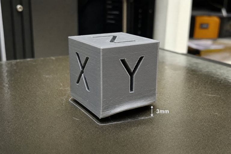
Before you disassemble anything, rule out defects that get mislabeled as Z-banding. Place your print under direct light and run a fingernail across the ridges.
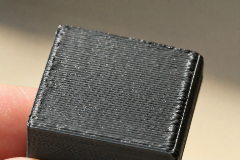
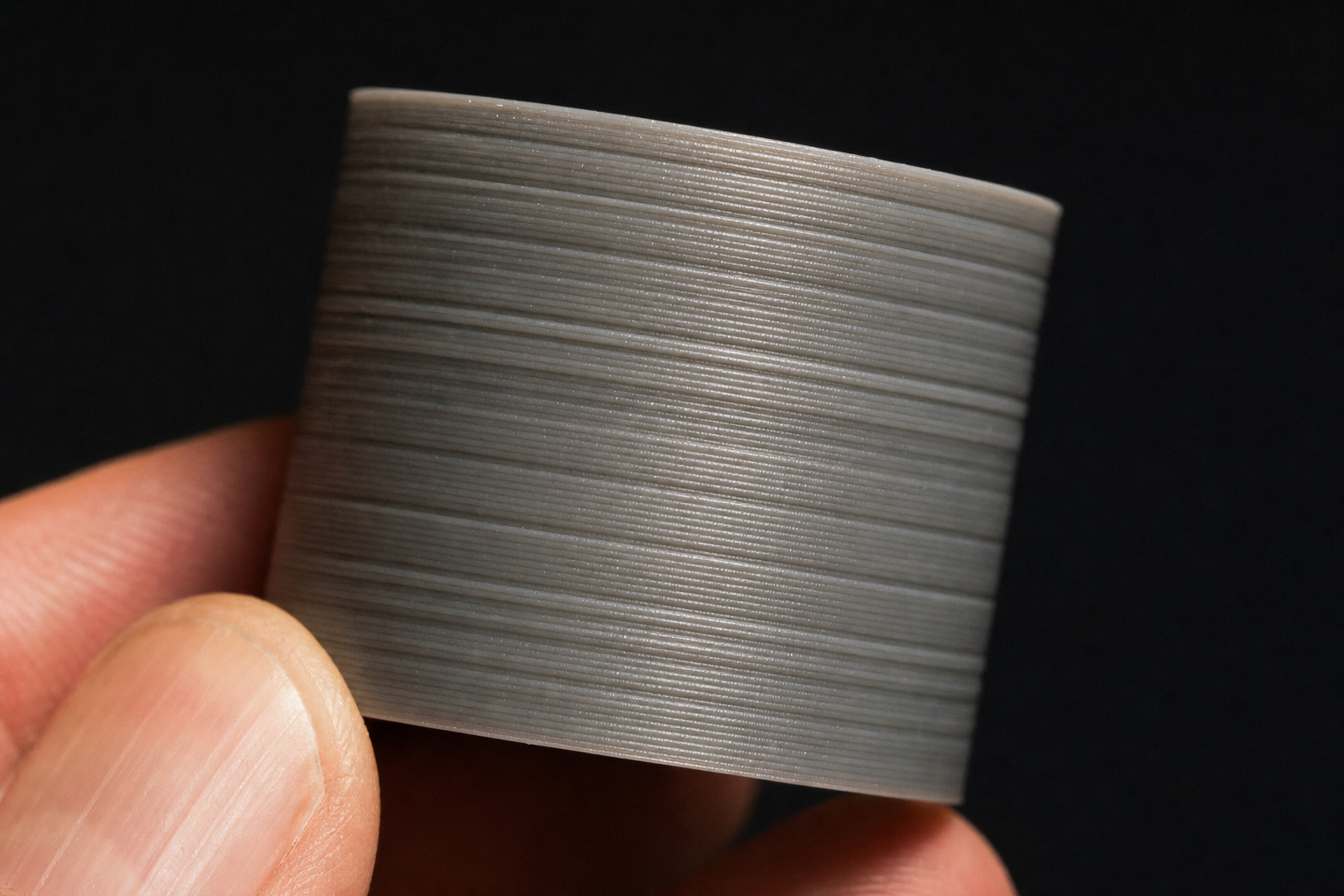
Z-banding produces a regular, repeating horizontal bulge that wraps around the entire perimeter. The interval between ridges stays consistent from bottom to top. If you measure the distance between ridges and find it equals 8mm, 2mm, or 4mm (common leadscrew pitches), you have mechanical Z-banding.
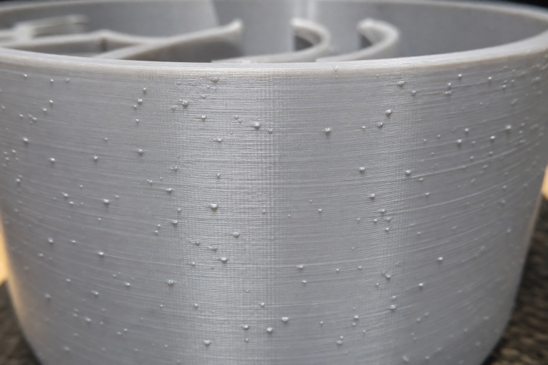
Inconsistent extrusion creates random surface roughness that does not repeat at fixed intervals. The texture looks more like scattered bumps than organized rings.
Layer shifts produce a single abrupt step, not repeating ridges.
One failure mode that catches people off guard: a slightly bent leadscrew can produce banding that only appears above a certain Z-height, where the bend starts binding against the brass nut. If your first 20mm look clean and then ridges appear, suspect a leadscrew that is straight near the coupler but bent higher up.
Ordered Mechanical Checks (Easiest First)
Work through these in sequence. Stop when you find the culprit.
1. Leadscrew Cleanliness and Lubrication
Dust, debris, and dried grease on the leadscrew threads create uneven friction as the nut travels. Wipe the leadscrew with a clean cloth and isopropyl alcohol, then apply a thin coat of PTFE-based dry lubricant or light machine oil. Avoid heavy grease—it attracts dust and creates sticky spots. If you don’t have PTFE lubricant, a drop of light sewing machine oil works; skip WD-40, which leaves a residue that collects grit.
Verification: After cleaning and lubricating, manually move the gantry through the full Z range by hand (motors off). It should feel smooth with no catching or tight spots. If a tight spot remains at the same height, the leadscrew is likely bent—jump to the bent leadscrew check.
2. Brass Leadscrew Nut Tension
The brass nut on the gantry should not be rigidly clamped. Most printers use two screws to mount this nut, and overtightening them prevents the nut from floating slightly to accommodate minor leadscrew misalignment. Loosen both screws, then tighten them just until they stop—no torque beyond that. You want the nut to have a tiny amount of lateral play.
Verification: With the screws backed off slightly, wiggle the nut by hand. It should shift a fraction of a millimeter side to side. If it is locked solid, it will transmit every leadscrew wobble directly into the print.
Branch point—what to do next depends on what you see after this adjustment. Print a quick 20mm tall test cylinder (vase mode if possible) and inspect the banding. If the ridges become noticeably softer or the interval shifts, the nut was overconstrained and you’ve found the main contributor. Gradually tighten the screws in tiny increments while printing another test until the banding disappears entirely. If the pattern remains identical in strength and spacing, the nut tension is not the primary cause—move on to coupler alignment.
3. Leadscrew-to-Motor Coupler Alignment
The flexible coupler between the Z motor and leadscrew can introduce wobble if the motor shaft and leadscrew are not coaxial. Look at the coupler while slowly moving Z up and down. If you see the coupler flexing or the leadscrew wobbling at the coupler end, the two shafts are misaligned.
Fix: Loosen the coupler grub screws, insert a spacer (a folded piece of paper works) between the motor shaft and leadscrew inside the coupler to maintain a small gap, then retighten. The gap prevents the leadscrew from bottoming out on the motor shaft and transferring motor vibration.
4. Bent Leadscrew Detection
Remove the leadscrew and roll it on a known flat surface like a glass bed or granite countertop. Watch the gap between the screw and the surface. Any visible wobble means the screw is bent. A bend as small as 0.1mm can produce visible banding because it translates into a layer height error at every rotation.
If bent: Replacement is the only reliable fix. Straightening a leadscrew by hand almost never restores it to the required tolerance. Budget leadscrews from printer manufacturers often ship with slight bends—consider upgrading to a higher-quality leadscrew from an industrial supplier if you are replacing one anyway. As a temporary workaround, you can rotate the leadscrew 180 degrees in the coupler to shift the bend’s influence to a different Z range, but this does not eliminate the error and may create new artifacts elsewhere.
5. Z-Axis V-Roller or Linear Rail Binding
On printers with V-roller wheels, eccentric nut adjustment that is too tight creates flat spots on the wheels and uneven motion. Adjust each eccentric nut until the wheel just barely stops free-spinning when you try to turn it by hand with the gantry stationary. It should grip enough to move the gantry without slipping, but no tighter.
On linear rail systems, check for gritty spots when moving the carriage by hand. A single damaged ball bearing in the rail block creates a repeating bind at one specific Z position. If you feel a consistent hitch at the same height, the rail block may need replacement.
Slicer Settings That Can Mimic Z-Banding
If your mechanical checks come up clean, two slicer settings can produce banding-like artifacts—but they create irregular patterns, not the fixed-interval ridges of true Z-banding.
Inconsistent extrusion from incorrect PID tuning: if your hotend temperature oscillates by more than 2–3°C during a print, the flow rate changes cyclically and can produce subtle horizontal lines. Run a PID autotune for your printing temperature (not just 200°C if you print at 215°C) and save the values. The lines from PID oscillation tend to be softer and less pronounced than mechanical banding.
Layer height that does not evenly divide into the Z motor’s full-step distance: most stepper motors have 200 full steps per revolution, and with a typical 8mm leadscrew, each full step moves the gantry 0.04mm. If you use a layer height like 0.15mm, the firmware must microstep between full steps, and microsteps are less accurate. Using layer heights that are multiples of 0.04mm (0.12, 0.16, 0.20, 0.24) keeps the motor on full steps at each layer and reduces microstep-induced errors. This is a subtle improvement, not a banding cure, but worth checking if your banding is faint and regular.
Verify the Fix with a Vase Mode Cube
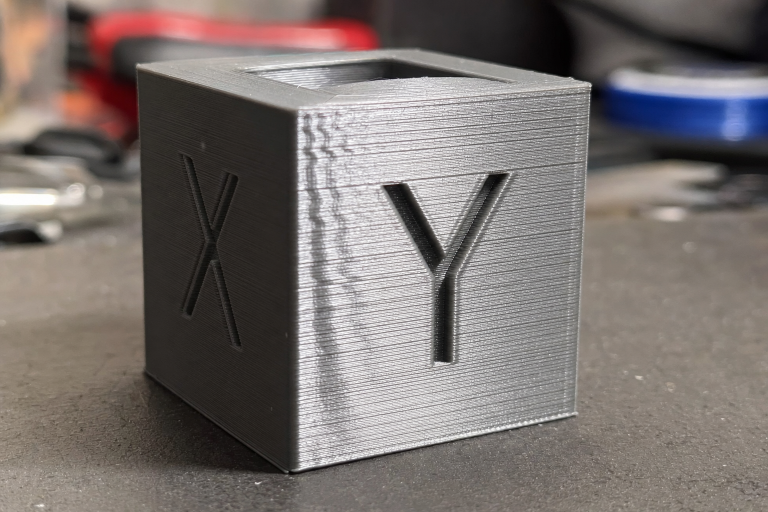
Print a 20mm calibration cube in vase mode (spiralize outer contour) to isolate Z-axis motion from retraction and infill artifacts. Vase mode eliminates seams, retractions, and travel moves, leaving only the Z motion visible.
A clean cube with smooth, unbroken vertical walls means your Z-axis is mechanically sound. If banding persists in vase mode, return to the mechanical checks—you missed something. If banding only appears in normal prints but not vase mode, your issue is extrusion-related: check PID tuning, filament diameter consistency, and extruder tension before revisiting slicer settings.
When to Stop and Escalate
Stop self-diagnosis and seek professional help if you hit this clear threshold:
You have replaced the leadscrew and brass nut, aligned the coupler, and lubricated everything, yet banding persists at the same regular interval. The fault is now beyond mechanical adjustment—the stepper motor may have a bent shaft, the driver may be delivering inconsistent current, or the mainboard may have a timing issue. Do not continue swapping parts blindly. Contact the printer manufacturer or a qualified repair service, especially if the printer is under warranty, as opening the motor or board can void coverage.
Additional red flags that mean it’s time to escalate:
- Banding appears only on one side of the print. This points to a gantry that is not square to the frame, causing the Z motion to bind asymmetrically. Tramming the gantry requires disassembly and precise measurement—beyond a quick fix.
- The banding interval does not match any leadscrew pitch and appears random. You may have a mainboard or driver issue producing inconsistent step pulses. Test with a different stepper driver if your board supports swapping them, but if you’re not comfortable with electronics, stop here.
Z-banding is almost always mechanical, and the fix is almost always in the leadscrew assembly. The majority of cases resolve with cleaning, lubricating, and loosening the brass nut screws. Start there, verify with a vase-mode cube, and only chase slicer settings if the mechanical path comes up completely clean.
Explore This Topic
- Back to Print Quality Defects
- Back to 3D Printing Troubleshooting Master Guide
Related guides in this cluster:
- Layer Shift: Causes & Complete Fix Guide for 3D Printing
- 3D Print Blobs & Zits: Retraction & Coasting Fix Guide
- Ghosting & Ringing: How to Eliminate Surface Artifacts
Ryan has been operating FDM 3D printers since 2017. He runs a 12-machine print farm. His daily drivers include a Bambu Lab X1 Carbon, Prusa MK4s, and Creality Ender-3 V3s that have logged over 15000 print hours. He started 3D Printer Nerd to provide structured troubleshooting guides with diagnostic order, material-specific parameters, and clear stop points.